Modern aerospace museums fail when they treat historic hardware as static sculpture rather than functional engineering solutions to specific physical constraints. The new L.A. Air and Space Center—anchored by the Samuel Oschin Air and Space Center expansion at the California Science Center in Exposition Park—resolves this failure by structuring its visitor experience around twelve distinct operational mechanisms of flight, orbital mechanics, and sensory simulation. Rather than relying on passive observation, the facility forces visitors of all cognitive stages to interact directly with the variables of thrust, drag, gravity, and human factors engineering. To extract maximum educational and experiential value from this campus, visitors must navigate the twelve primary exhibits not as an arbitrary checklist, but as a structured progression through four distinct engineering domains: Heavy-Lift Orbital Hardware, Atmospheric Aerodynamics, Kinesthetic Simulation, and Deep-Space Telemetry.
Domain I The Mechanics of Heavy-Lift Orbital Hardware
The foundational error in conventional science communication is divorcing the scale of an aerospace vehicle from the thermodynamic realities required to move it. The L.A. Air and Space Center corrects this by presenting full-scale flight hardware in configurations that expose their structural load paths and propulsion architectures.
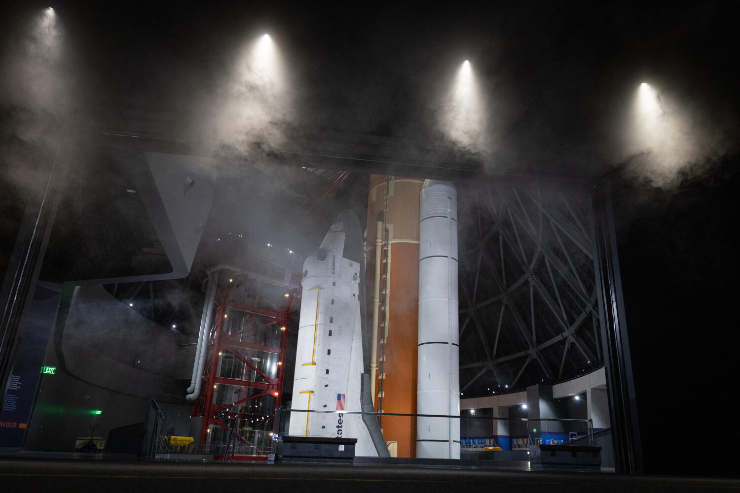
1. The Vertical Launch Stack of Space Shuttle Endeavour
Displaying the Space Shuttle Endeavour in a vertical, launch-ready configuration—mated to an authentic External Tank (ET-94) and two Solid Rocket Boosters (SRBs)—transforms a familiar silhouette into a visceral lesson in mass-to-orbit ratios. When viewed horizontally, an orbiter appears aerodynamic; when stacked vertically to a height of 200 feet, the engineering reality becomes unavoidable. The orbiter itself represents a fraction of the total vehicle mass at liftoff. Visitors observing the stack from the multi-level viewing gantries confront the tyranny of the rocket equation directly: roughly 85 percent of the launch vehicle's mass consists solely of propellant and the structural tankage required to contain it. The vertical orientation allows observers to trace the exact mechanical attachment points—the forward and aft attach struts—where millions of pounds of thrust from the SRBs transfer into the external tank structure before lifting the orbiter clear of the pad.
2. Space Shuttle Main Engine (RS-25) Nozzle and Turbopump Architecture
Adjacent to the full stack, isolated displays of the RS-25 engine strip away the thermal protection blankets to expose the regenerative cooling channels and high-pressure turbomachinery. Most visitors assume rocket nozzles are solid blocks of heat-resistant alloy. Close inspection reveals hundreds of microscopic milled channels running vertically along the inner wall of the bell. During operation, liquid hydrogen at minus 423 degrees Fahrenheit circulates through these channels before entering the combustion chamber, preventing the 6,000-degree Fahrenheit exhaust plume from melting the metallic structure. This single exhibit illustrates a foundational principle of aerospace design: energy recovery through thermal management.
3. The Korean Air Aviation Gallery Aircraft Suspension Matrix
Transitioning from orbital mechanics to atmospheric flight, the aviation gallery suspends historic and experimental airframes—including the Northrop F-20 Tigershark and early Douglas commercial transports—along calculated pitch, roll, and yaw vectors. Instead of hanging aircraft level to the floor, the rigging demonstrates aerodynamic trim and angle of attack. By positioning an interceptor in a high-alpha climb directly above a high-aspect-ratio glider, the spatial arrangement forces an immediate visual comparison between wing loading, sweep angle, and energy maneuverability. High-speed interceptors minimize wing area to reduce wave drag at supersonic velocities, accepting high landing speeds as a trade-off. Gliders maximize wingspan to reduce induced drag, trading speed for lift-to-drag efficiency.
Domain II Atmospheric Aerodynamics and Fluid Dynamics
Children and adults frequently struggle to conceptualize air as a physical fluid with mass, viscosity, and compressibility. The facility's second operational tier translates invisible fluid dynamics into tactile feedback loops.
4. Interactive Subsonic Wind Tunnel Arrays
Rather than relying on animated diagrams of Bernoulli’s principle, the center deploys closed-loop subsonic wind tunnels equipped with smoke-stream generators and real-time force balances. Visitors manipulate the angle of attack on physical airfoils while observing the boundary layer separation in real time. Pushing the airfoil past its critical angle of attack causes the laminar smoke streams to detach from the upper camber and curl into turbulent eddies, accompanied by an immediate drop on the digital lift gauge and a spike on the drag readout. This direct cause-and-effect manipulation demystifies aerodynamic stall far more effectively than text panels ever could, proving that stall is a function of angle rather than airspeed.
5. Supersonic Shockwave and Schlieren Imaging Stations
Breaking the sound barrier alters the fundamental behavior of air, shifting it from an incompressible fluid to a compressible medium where pressure disturbances cannot propagate upstream of the aircraft. The center utilizes optical Schlieren photography setups—which detect minute variations in air density through light refraction—paired with small-scale supersonic blowdown nozzles. Visitors trigger high-pressure air bursts over wedge and cone geometries, viewing the resulting oblique and bow shockwaves on high-contrast monitors. Adjusting the Mach number of the flow visibly changes the shock angle, demonstrating the exact trigonometric relationship between vehicle velocity and the Mach cone.
6. Variable-Pitch Propeller and Rotorcraft Thrust Rigs
Understanding rotary-wing flight requires grasping vector control. The rotorcraft exhibits place visitors at the cyclic and collective controls of a tethered, shrouded rotor assembly. Pulling the collective increases the pitch angle of all blades simultaneously, increasing total thrust and lifting the assembly along a vertical guide rail. Tilting the cyclic alters the blade pitch selectively as each blade passes through a specific azimuth, tilting the thrust vector and inducing horizontal translation. For younger visitors, this converts the abstract concept of vector addition into a physical balancing act, requiring continuous micro-adjustments to maintain a stable hover against simulated crosswinds.
Domain III Kinesthetic Simulation and Human Factors
Aerospace engineering is constrained not merely by metallurgy and propellant chemistry, but by the physiological limits of the human operator. The third category of experiences places the visitor inside the control loop, subjecting their vestibular and cognitive systems to operational stressors.
7. Multi-Axis Spatial Disorientation Trainers
Pilot error in instrument meteorological conditions frequently stems from vestibular illusions—specifically the somatogravic and Coriolis illusions, where inner-ear fluid lags behind rotational acceleration. The center's multi-axis gimbal simulators isolate the rider from external visual references while executing controlled pitch and roll rotations. Riders are tasked with identifying their true orientation using a joystick before the canopy opens to reveal their actual physical attitude. The discrepancy between perceived motion and true orientation provides an unforgettable lesson in why instrument flight rules require pilots to trust calibrated gyroscopes over biological sensory inputs.
8. High-G Centrifuge Force Demonstrators
While public museum installations cannot safely subject minors to sustained 9-G combat maneuvers, scaled-down human-rated centrifuges and comparative mass-loading rigs demonstrate the physiological mechanics of radial acceleration. Visitors experience moderate lateral G-loads while attempting basic motor tasks, such as depressing target buttons on a console. Simultaneously, adjacent telemetry displays illustrate how anti-G straining maneuvers and pneumatic G-suits apply mechanical pressure to the lower extremities to prevent blood pooling away from the cerebral cortex.
9. Full-Motion Shuttle Re-entry and Landing Simulators
Landing an unpowered, 100-ton delta-wing glider from orbital velocity requires executing a precise energy-management profile with zero margin for a go-around. The center’s full-motion simulators replicate the final approach phase of a Space Shuttle landing, starting at 10,000 feet with a 20-degree glideslope—roughly seven times steeper than a commercial airliner. Operators must manage speedbrakes to bleed off excess kinetic energy while executing a pre-flare maneuver at 2,000 feet to arrest the sink rate before touchdown. Failing to manage energy early in the approach results in either undershooting the runway threshold or overshooting the stopping distance, illustrating the unforgiving nature of unpowered terminal guidance.
10. Extravehicular Activity (EVA) Pressurized Glove Boxes
The vacuum of space turns a flexible garment into a rigid pressure vessel. To communicate the physical exhaustion astronauts endure during spacewalks, the center embeds heavy-duty, pressurized EVA gloves into transparent vacuum chambers. Visitors insert their hands into the gloves—which are pressurized to simulate the 4.3 psi differential of a standard spacesuit—and attempt to thread standard aerospace bolts or manipulate electrical connectors. The constant restorative force of the pressurized bladder fights every finger flexion, converting a ten-second terrestrial task into an isometric forearm workout.
Domain IV Deep-Space Telemetry and Robotic Autonomy
Beyond Low Earth Orbit, human presence yields to robotic proxies governed by light-speed communication delays and extreme thermal environments. The final tier of exhibits shifts the visitor from direct pilot to mission controller.
11. Time-Delayed Planetary Rover Teleoperation Courses
Operating a rover on Mars precludes real-time joystick control due to the one-way light-time delay, which ranges from three to twenty-two minutes depending on orbital alignment. The center replicates this operational constraint on a simulated Martian regolith terrain course. Visitors must plot a multi-waypoint navigation path using stereo camera feeds, transmit the command sequence, and wait through a compressed, yet perceptibly frustrating, signal latency period while the rover executes the commands autonomously. If the operator fails to account for wheel slip on loose inclines or rock hazards outside the immediate camera field of view, the rover halts on a fault condition, forcing a complete recalculation of the command sequence.
12. Infrared Thermal Imaging and Spacecraft Shielding Walls
In the absence of an atmosphere, heat transfer in space occurs almost exclusively through thermal radiation. Visitors stand before an array of spacecraft thermal protection materials—including silica-fiber shuttle tiles, multi-layer insulation (MLI) gold Kapton foils, and carbon-carbon composites—while high-intensity thermal lamps heat the front surfaces. Long-wave infrared cameras project real-time thermal maps onto overhead screens, allowing visitors to place their hands on the rear face of a heated shuttle tile while the front face glows at extreme temperatures. This visual and tactile contrast proves how low thermal conductivity and high surface emissivity protect sensitive electronics and crew compartments from the violent thermal cycling of orbital sunrise and sunset.
Operational Limitations and Strategic Visitor Execution
A museum environment inherently compresses and sanitizes extreme physical phenomena to ensure public safety and throughput capacity. Consequently, visitors must recognize three structural limitations in these exhibits. First, the motion-base simulators and centrifuges operate within strict civil liability envelopes; they replicate the directional cues and visual workload of flight, not the crushing sustained acceleration or acoustic shock of an actual launch. Second, high-throughput interactive stations—particularly the wind tunnels and rover courses—suffer from queue bottlenecks during peak weekend hours, reducing individual dwell time and limiting iterative experimentation. Third, static hardware displays like the Endeavour stack require active spatial visualization from the viewer to appreciate internal systems hidden beneath thermal tiles and structural skin.
To bypass these bottlenecks and maximize cognitive retention across age groups, execute a reverse-flow routing strategy upon arrival. Immediately bypass the ground-floor introductory galleries at opening, as 80 percent of incoming foot traffic congregates at the first interactive stations they encounter. Proceed directly to the upper-level Endeavour viewing gantries and the RS-25 engine displays while crowd density is near zero, establishing the macro-scale engineering context first. Once the primary galleries reach peak saturation around mid-morning, transition to the kinesthetic simulators and wind tunnels during the midday lunch window, when family groups cycle out of the exhibit halls. Finally, anchor every interactive station with a single predictive question before allowing children to touch the controls: ask what will happen to the airflow, the rover, or the glider when a single variable changes. Force the hypothesis first, execute the mechanical test second, and observe the physical outcome third.